Passionate and results-driven mechanical engineer with 4 years of experience in consumer electronics, specializing in product design and manufacturing. I thrive at the intersection of innovation and practicality, turning ideas into high-quality, manufacturable products that make a real impact.
Outside of engineering, I love lifting weights, playing volleyball, and eating good food.
An open source project that incorporates a 1/16th scale RC car, raspberry pi 3b+, and python in order to
create a self-driving car that can be trained on different tracks.
This project was a part of the MAE 106 coursework
at UCI where students built controllers and competed
against each other in an online game called Agar.io.
A personal project which I undertook in order
to get a better look at my weightlifting progress
as well as to better understand how to work with data.
Agario Controller
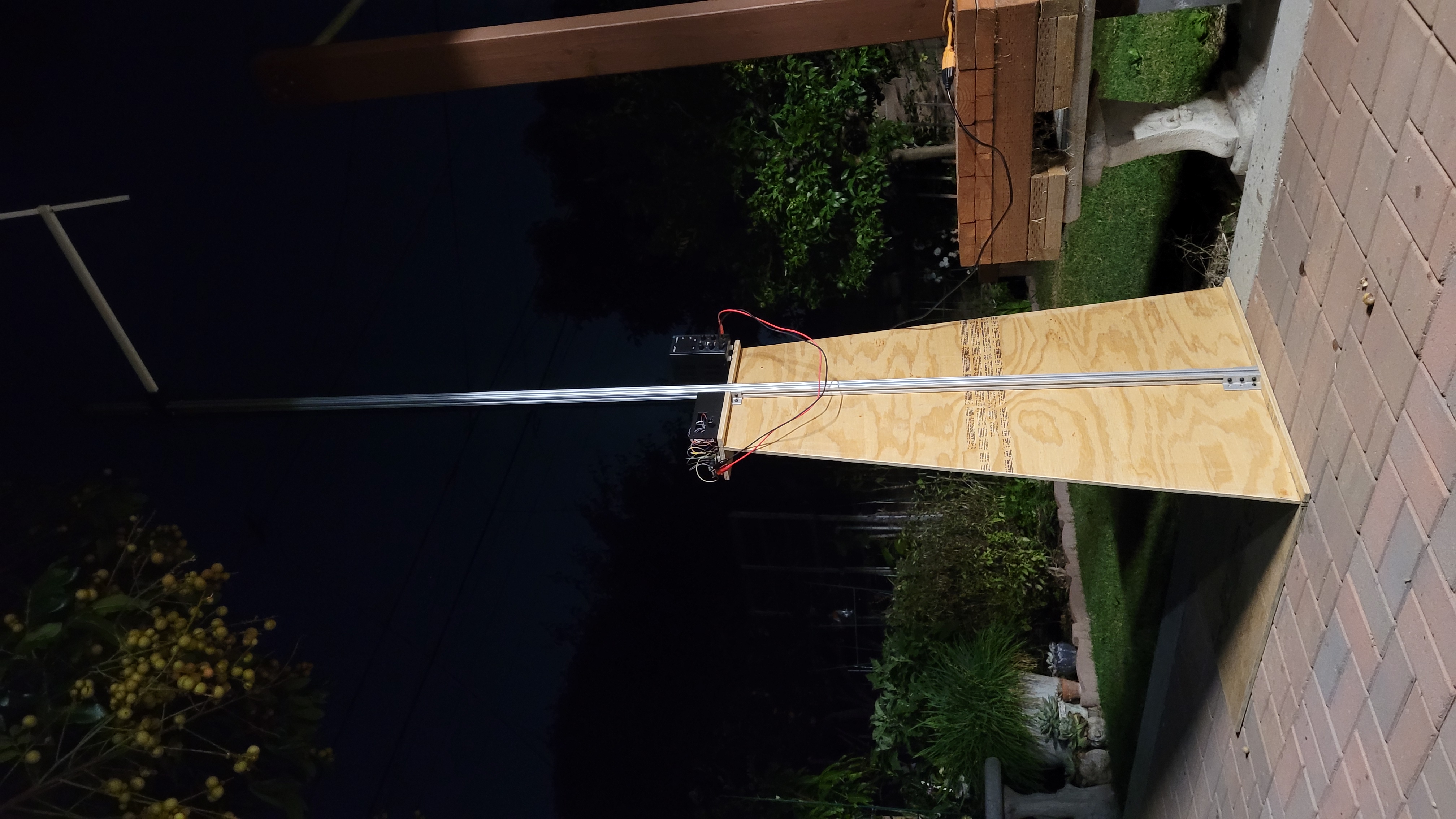
This project was an accumulation of the variety of topics learned in UCI's MAE 106
Mechanical Systems Lab course and had two main parts: designing/modeling a
hopper car and creating a controller which would control a simulation of the car.
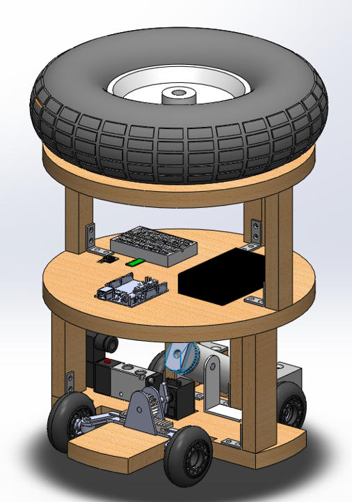
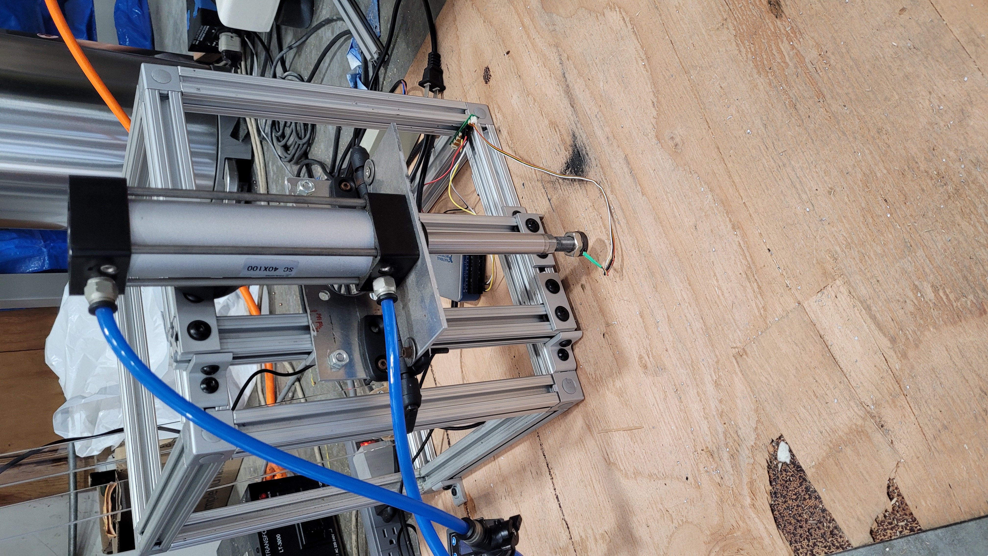
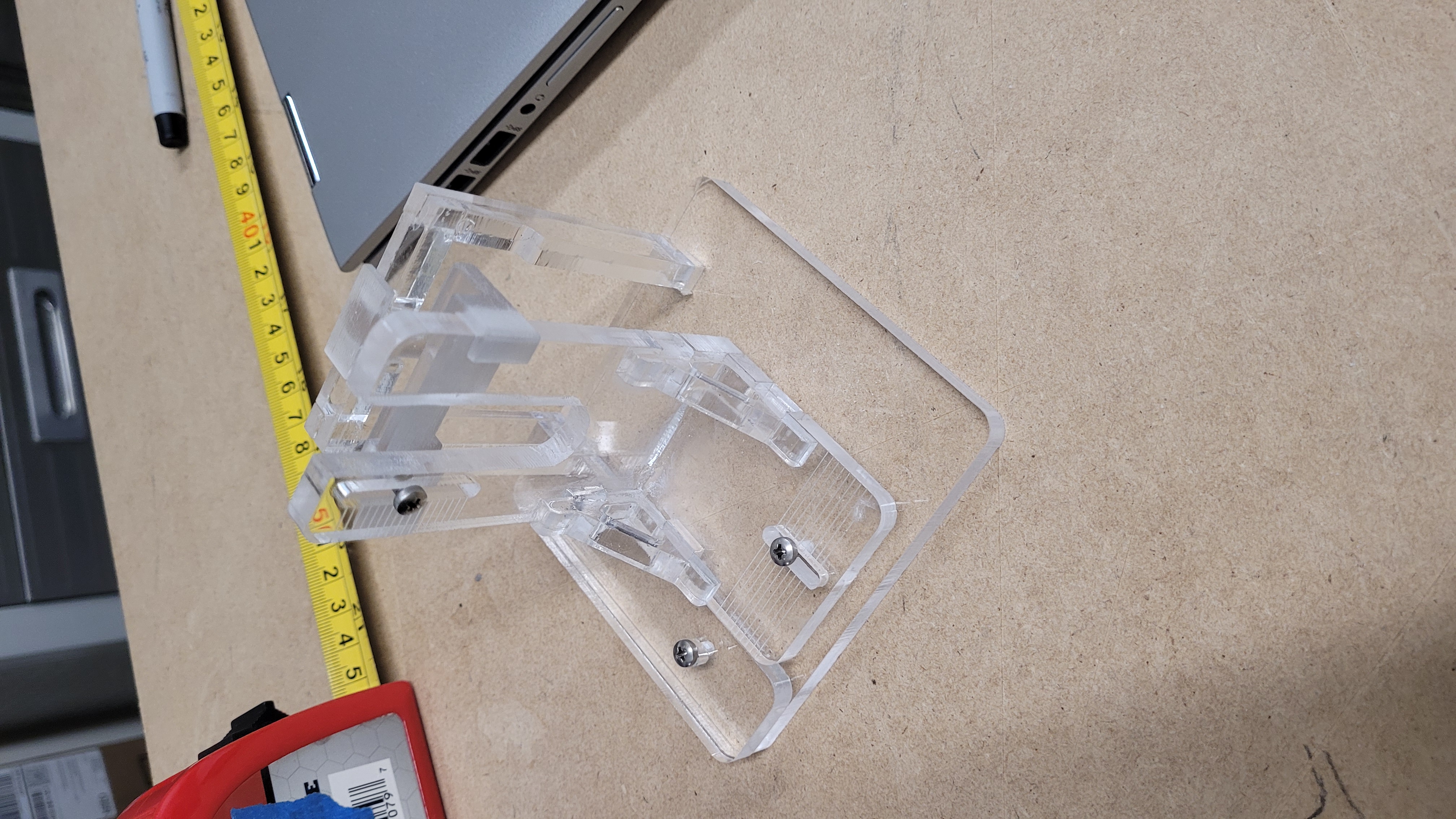
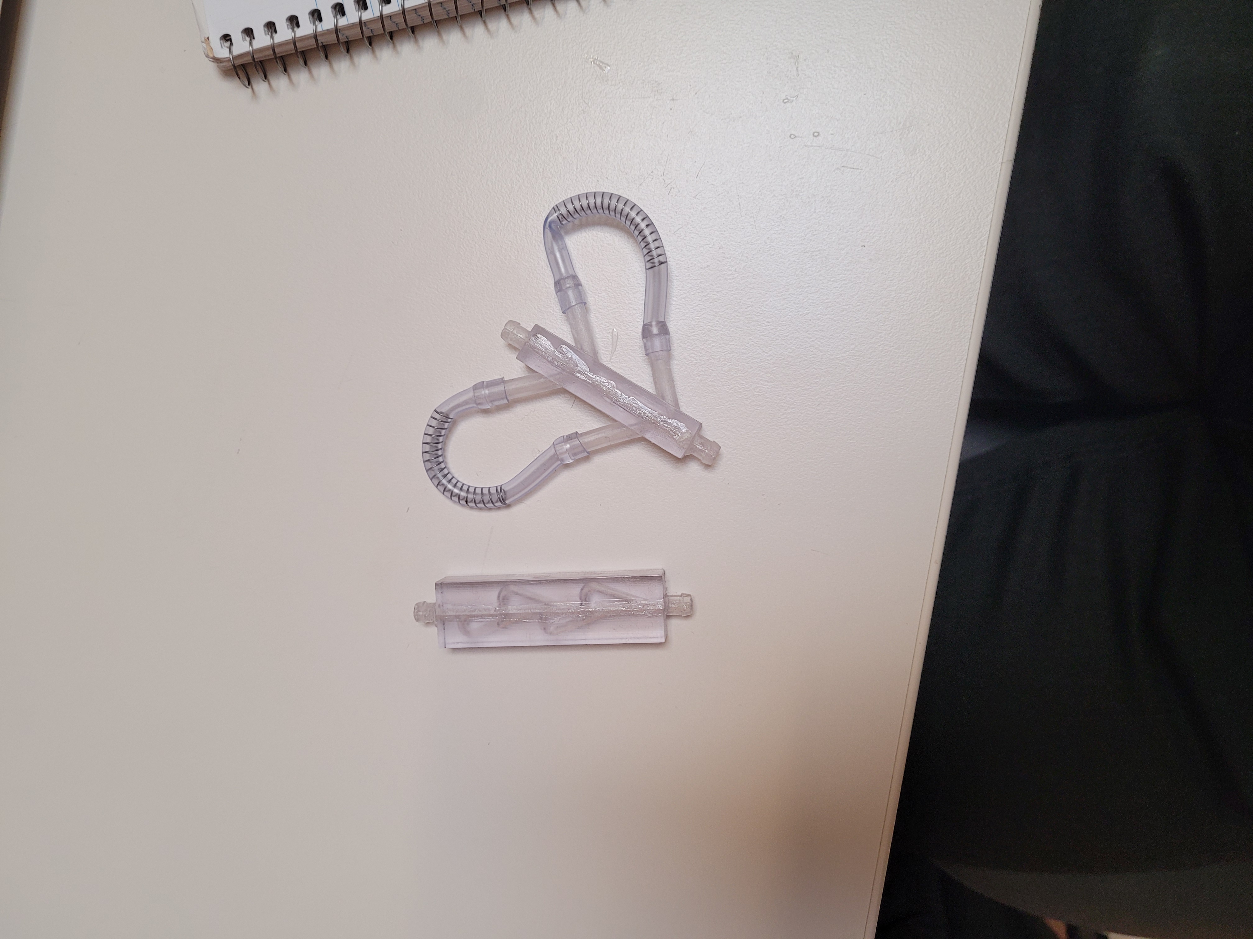
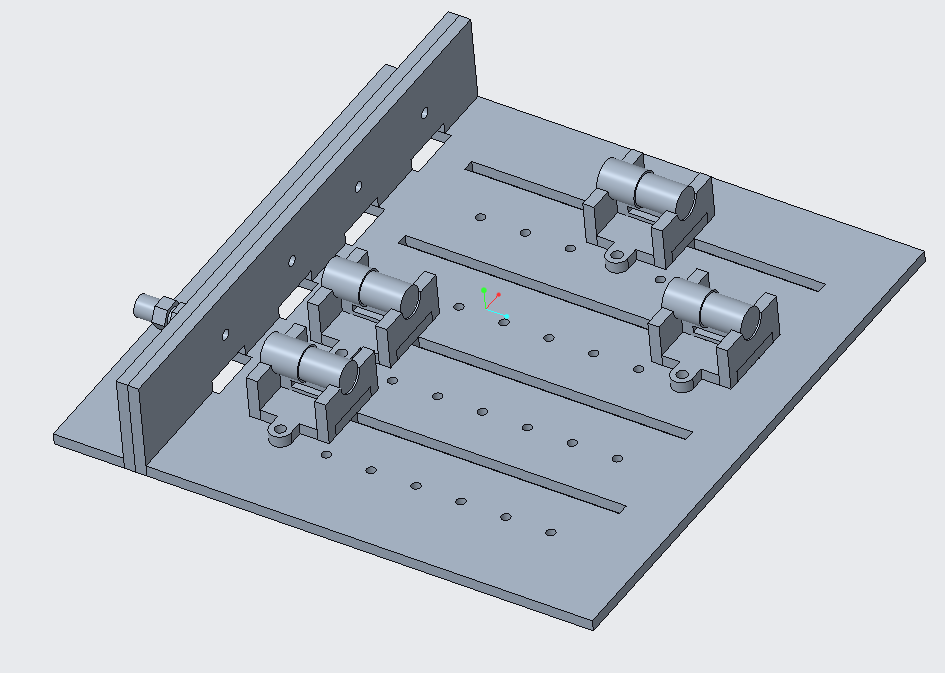
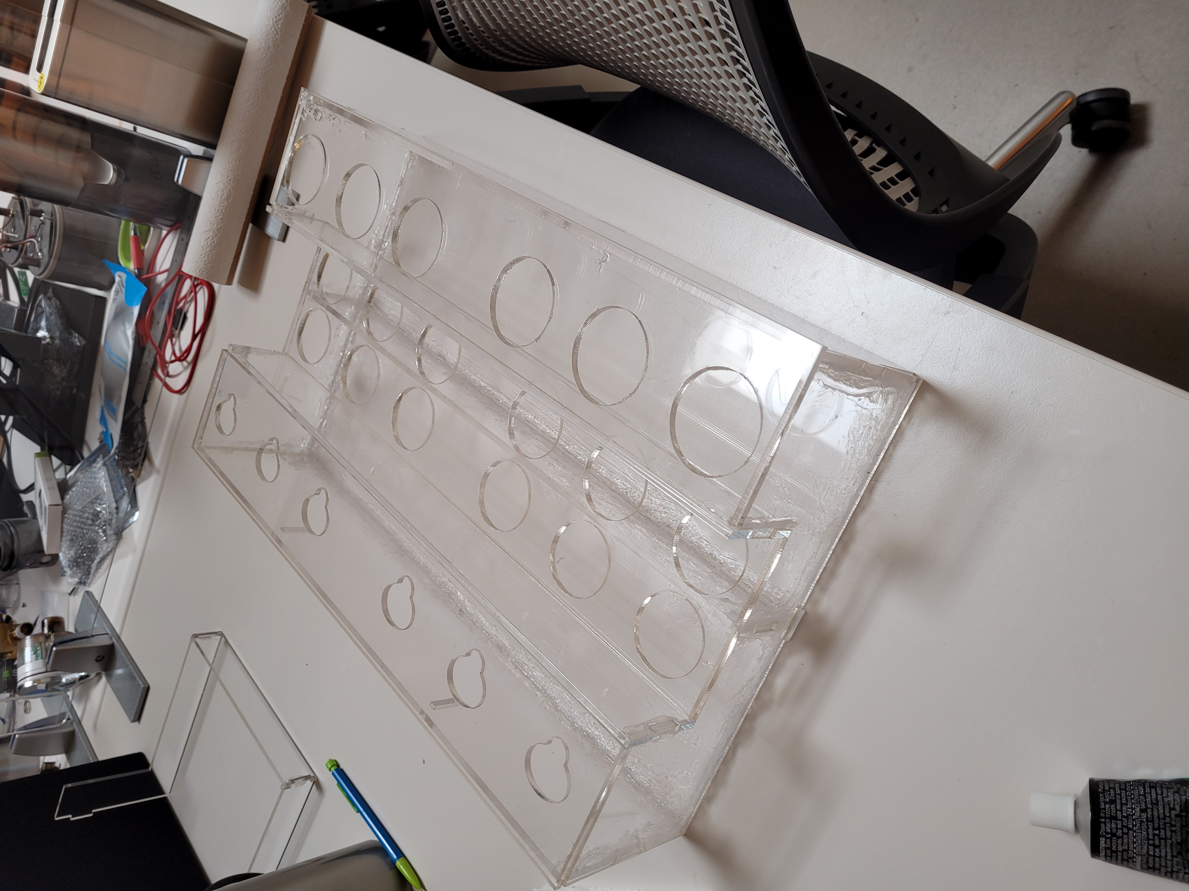
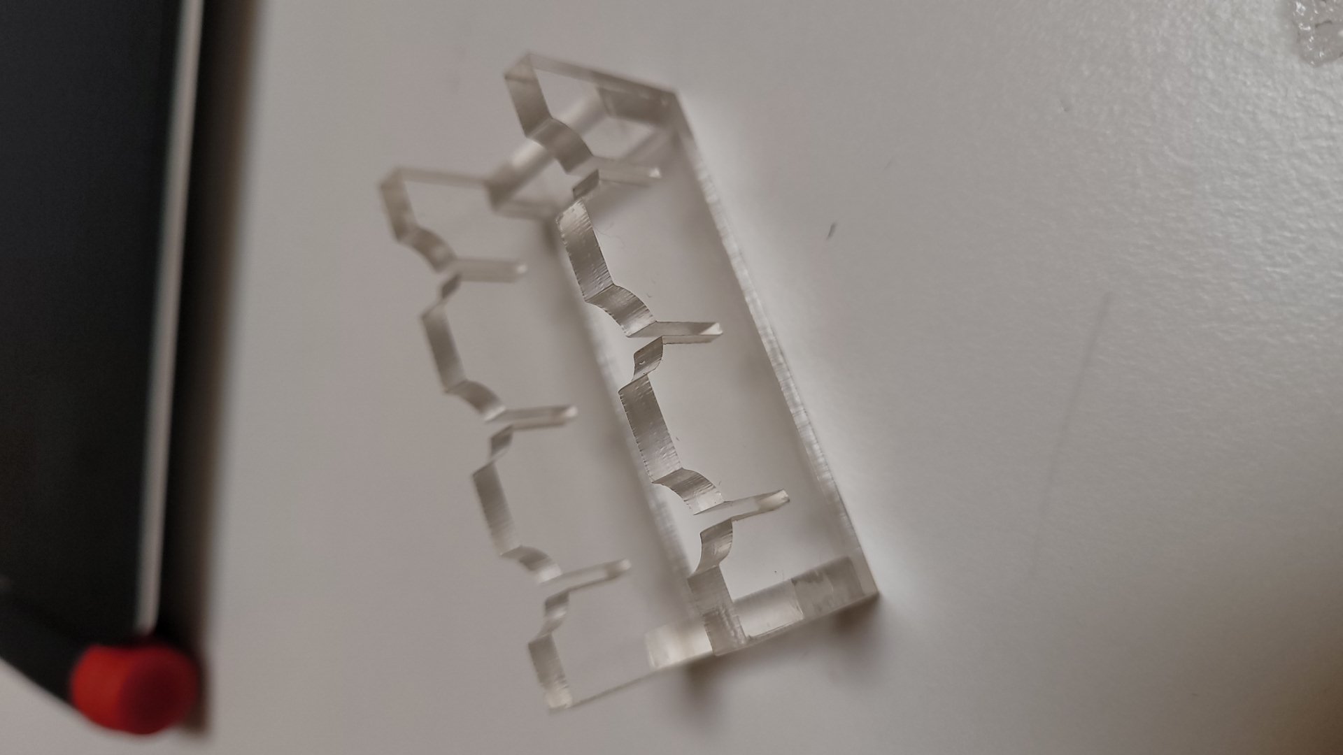
In groups of three, we designed a car based off of three major sections: chassis,
propulsion, and steering. I aided with chassis and propulsion, but I was primarily
responsible for developing the steering system in which I chose a rack and piston
steering system which utilized Ackermann steering geometry. I chose this steering
system for its ease of implementation in relation to its effectiveness based off of
the parts we had.
The controller was the second part of the project in which students were told to
create a controller to control a computer mouse and steer a
blob resembling the car in a game called agar.io.
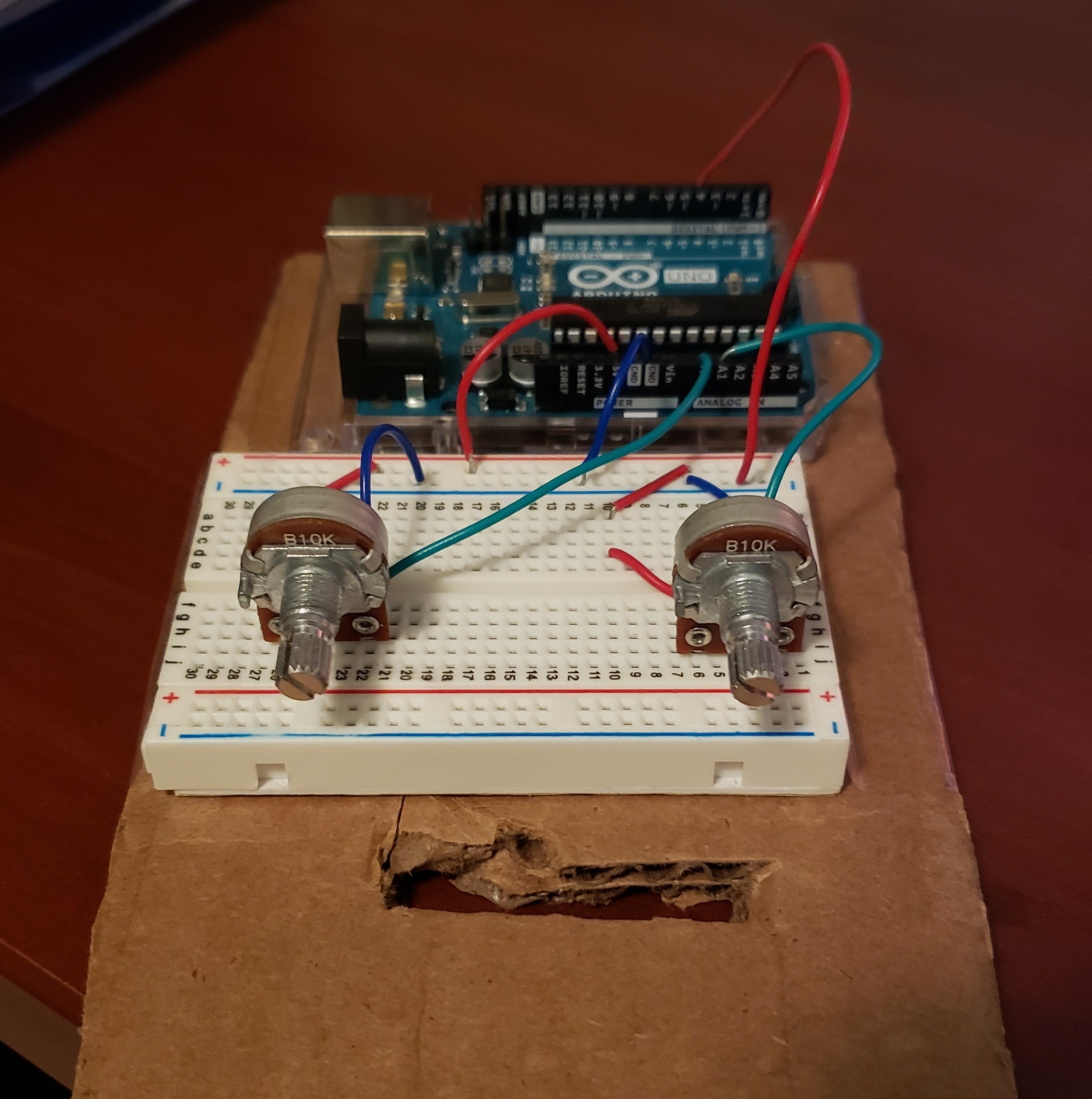
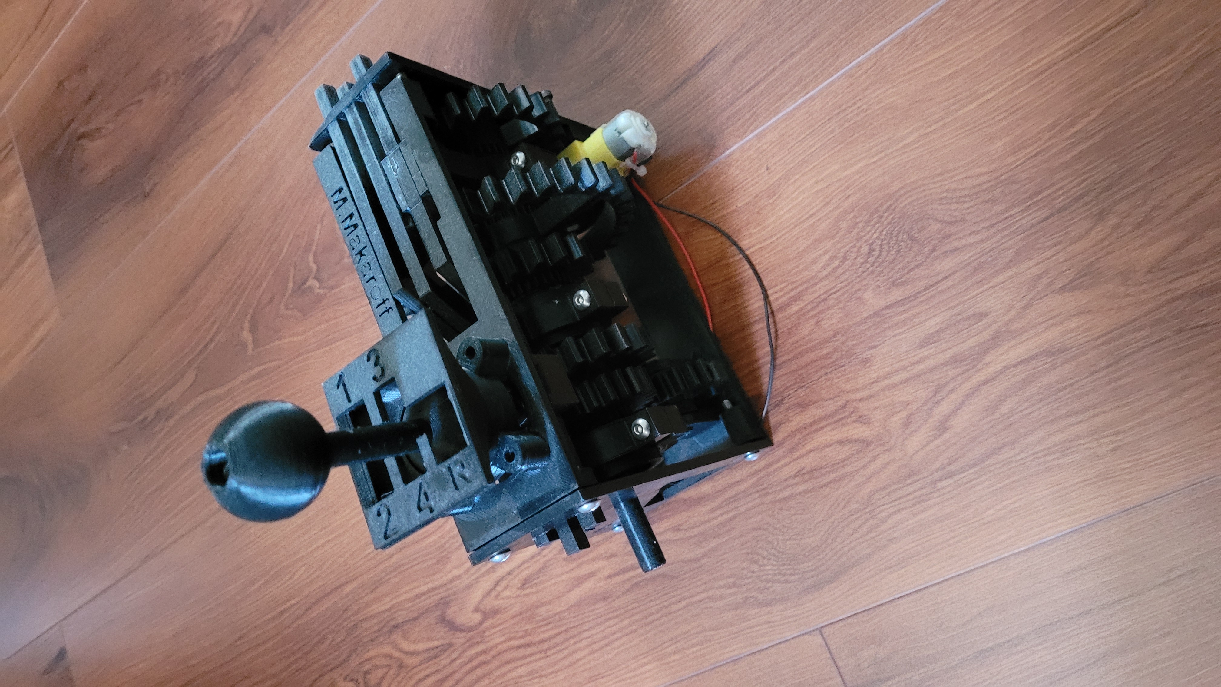
I personally chose to use a proportional controller with a high gain rate to
allow for simple yet responsive steering based off of the value of the left
potentiometer shown above. The right potentiometer above served to control the speed
of the car which varied the distance the mouse traveled in front of the blob
in the game. I created a three speed system which would allow me to carefully
control the amount of air expended so that I could outlast the other students
in our competitions held at the end of the course. Due my design choices and a bit
of luck, I managed to place 6th out of over 200 students.
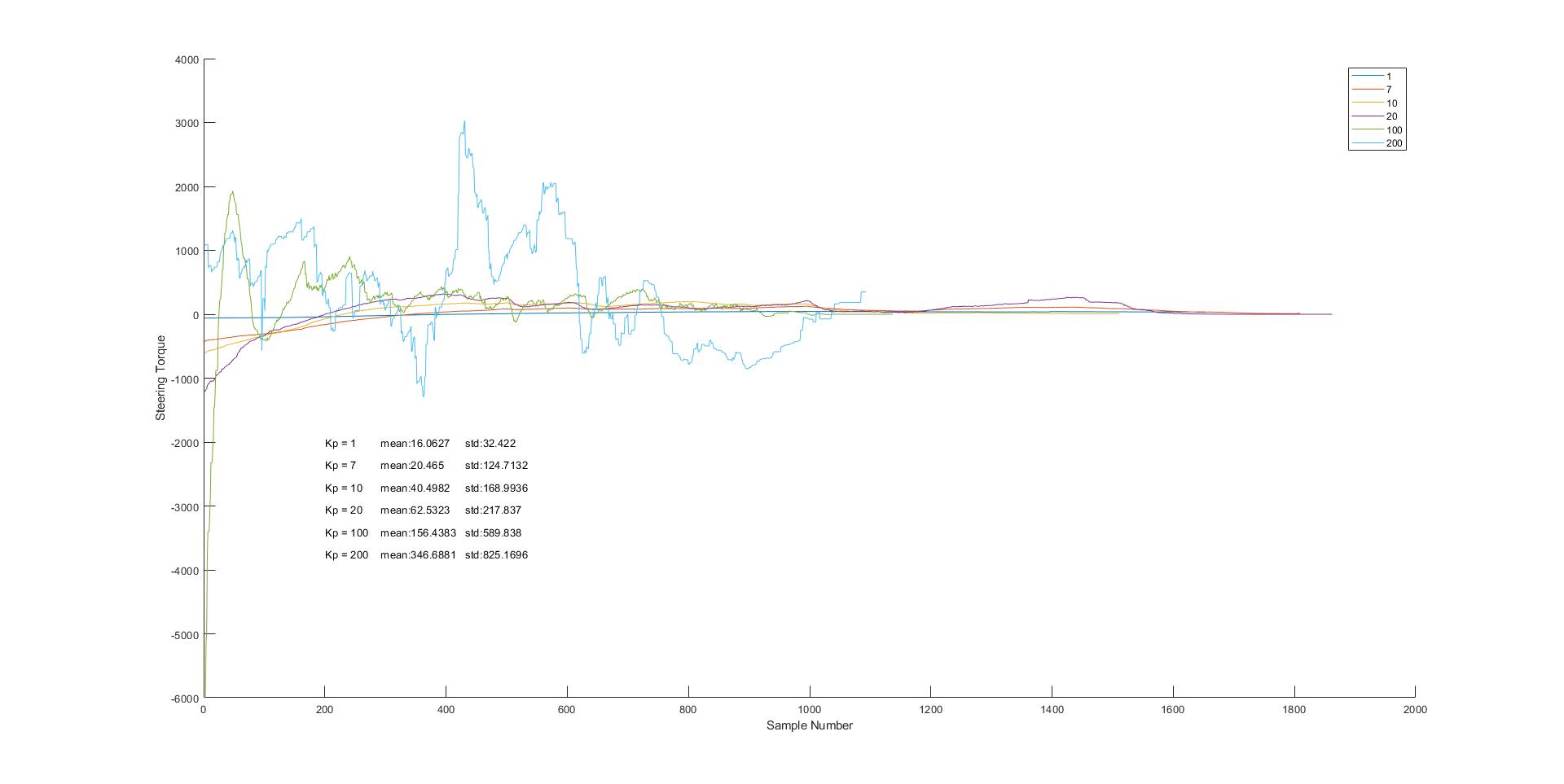
Using MATLAB, I plotted the simulation steering torque with different gain rates
and ended up using a gain of 100. This was due to the fact that when actually using
the controller to play agar.io, the overcompensations from the large gain allowed me
to reach my desired angle much quicker without too much oscillation.
This is a personal project of mine which I undertook in order to better understand my progress in my hobby of weightlifting.
I imported the data from a workout tracker app in the form of a CSV file and manipulated the data such that I could visualize and
organize certain aspects of particular exercises. I came up with several functions that displayed important information relevant
to lifting weights such as one rep maxes and volume.
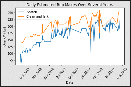
The chart above displays the estimated one rep maxes for a given lift based on the Epley formula.
This chart was made through three different functions: one to create a data frame of the exercise
name, weight, and rep count, another to estimate the rep max, and a third to plot the data. In the
data frame function, I calculate the rep max for each set in a day's workout and take the highest per
day which gets appended to a list and returned.
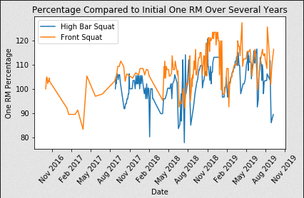
The chart above displays the percentage increase of my one rep maxes from the first rep max estimate.
It was done in a similar fashion to the chart prior but with the addition of the minor calculation of
dividing the rep maxes by the first given max.
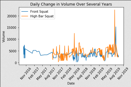
This chart above displays the daily volume for a certain exercise where volume is equal to the
reps x sets x weight. This is a measure used in weightlifting to see how much work is being done
within a training cycle. This was accomplished through creating a data frame of weight and reps
and the summing the total per day which is then added to a list.
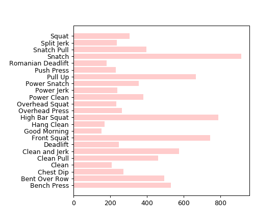
Lastly, the graph shows the total number of sets for the most popular exercises above a certain set count
which in this case was 150 sets.
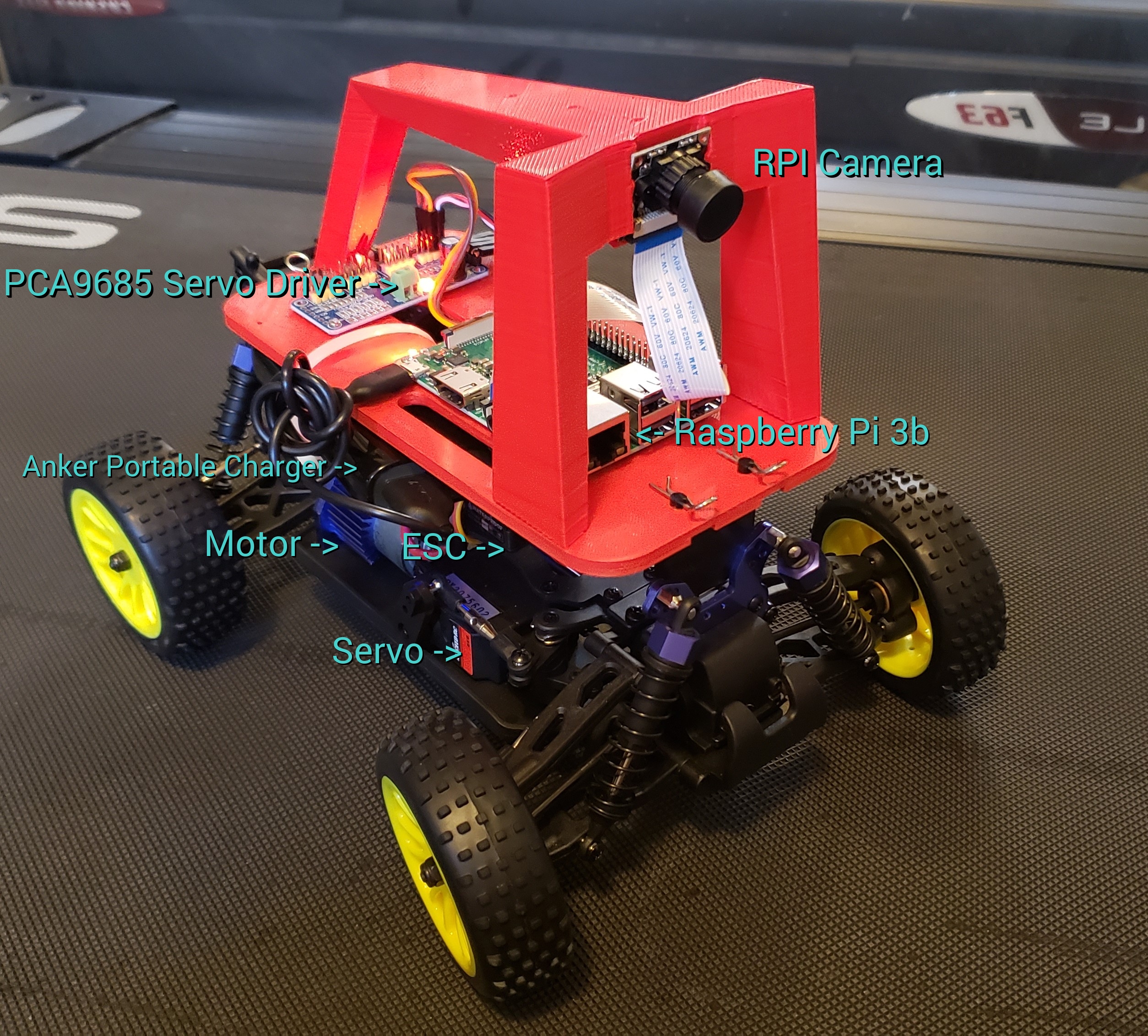
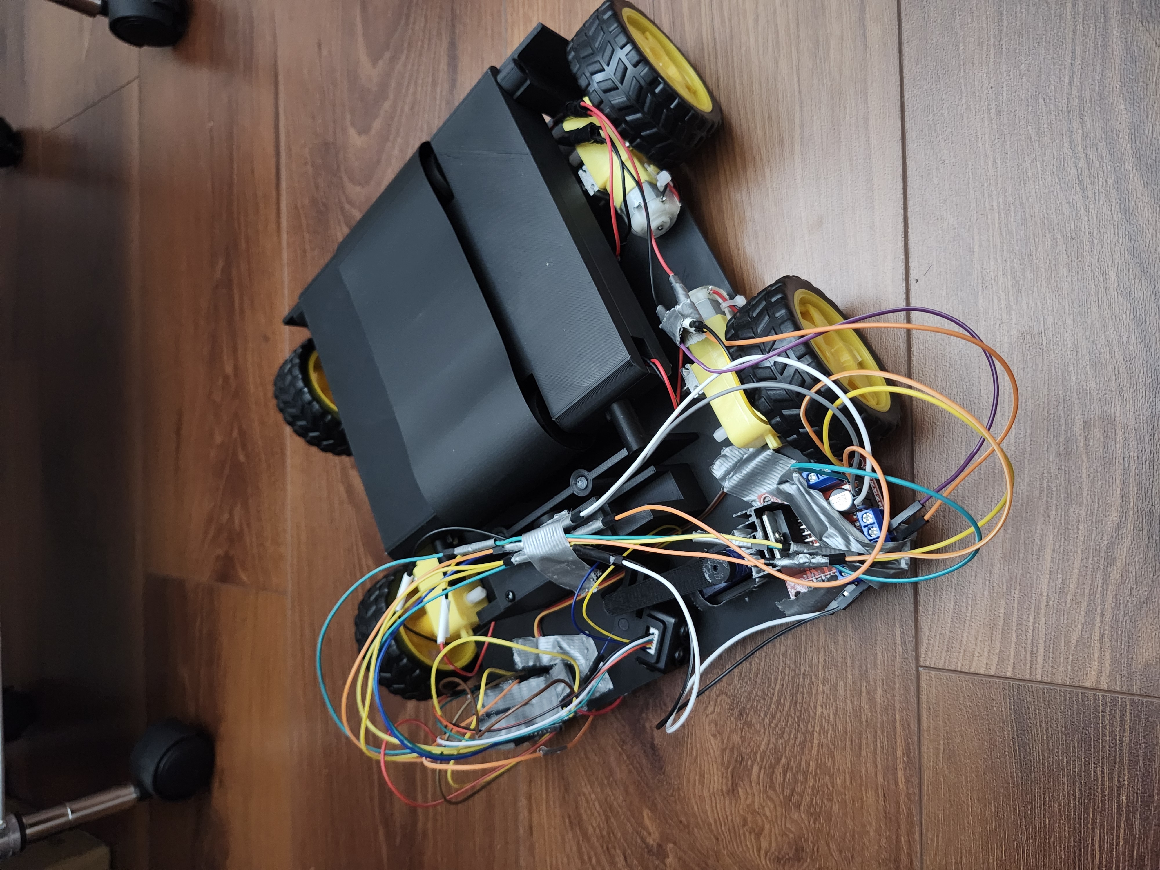
This is my donkeycar which was built using a standard 1/16th RC car (Exceed RC Blaze), a raspberry pi 3b+, and a donkeycar kit which contained the servo driver, camera, and 3D printed parts. After collecting data from the camera, Keras was utilized to create a self-driving model and traffic sign classification.
Above are videos of the car in autopilot mode (left) and what the car saw through the RPI camera (right).
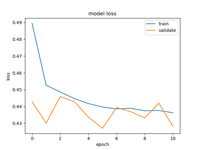
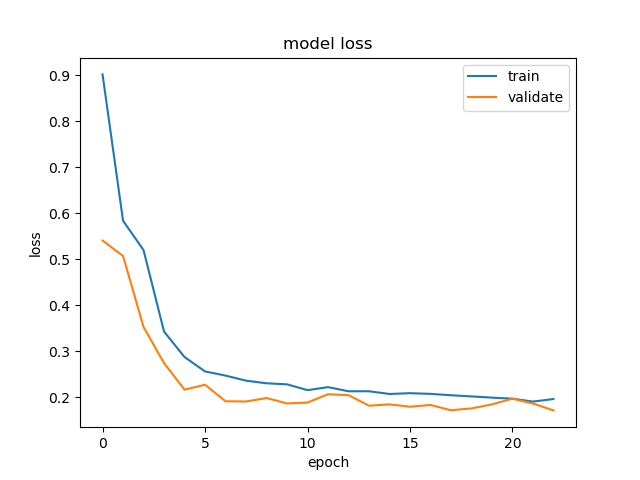
The two charts above are of two different sets of data from the same track. I collected data by driving the donkeycar around the track about 15 times for each dataset using a playstation 3 controller. The chart on the left shows my first attempt at collecting data which was admittedly poor and caused the autopilot to crash frequently. However, on the second try I collected much better data which resulted in the car driving smoothly within the bounds of the track. Using the data from the second attempt, I trained different models including linear, 3D, RNN, categorical, and latent in which the latent model performed the best.
The video above shows a side project using the donkeycar's camera, ROS, yolov3, and Keras. The traffic sign detection and classification models were created by modifying and merging code from two different people, Murtaza Hassan and Sergio from Pysource (links at bottom). Then I implemented ROS to relay information from the camera by subscribing to the raspicam_node topic. I intended to then use ROS to implement low level control for the car based off the specific traffic signs being seen, however, the framerate from the camera was far too low for it to be us
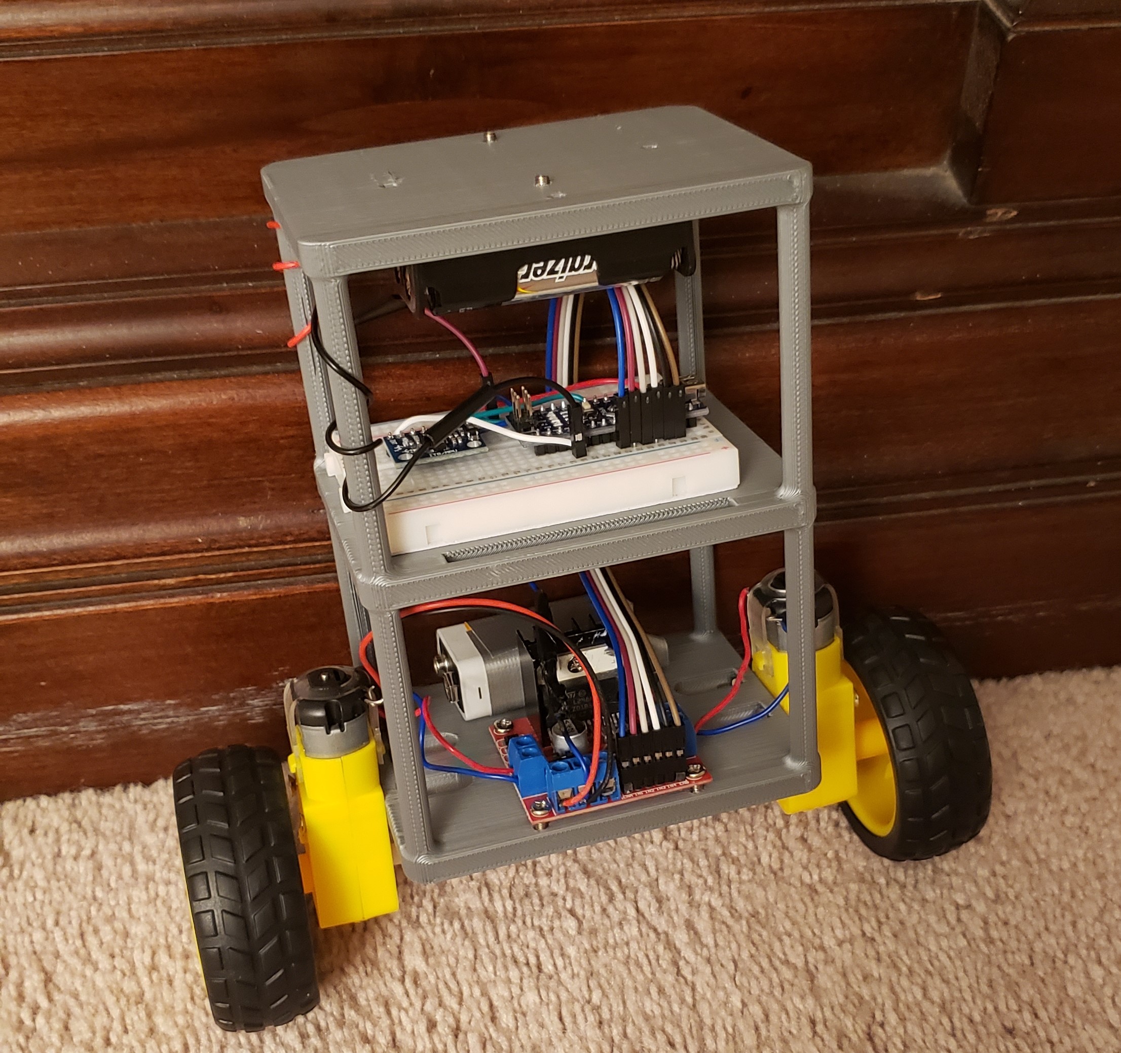
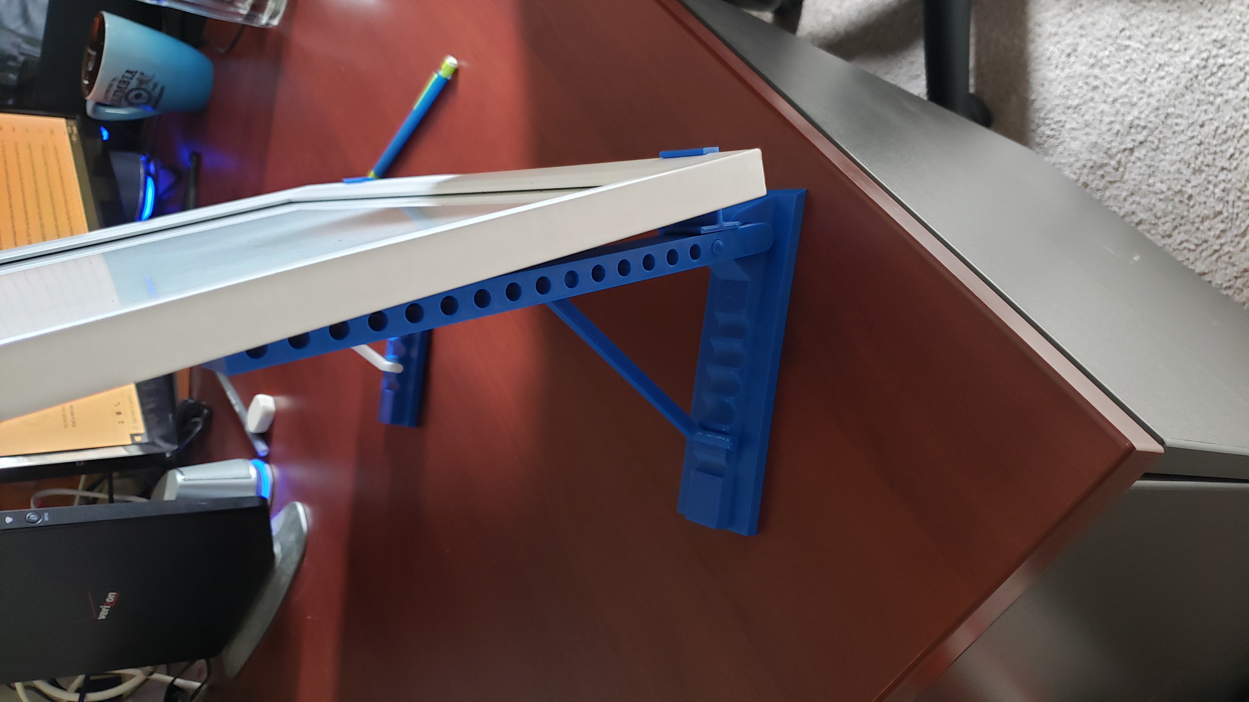
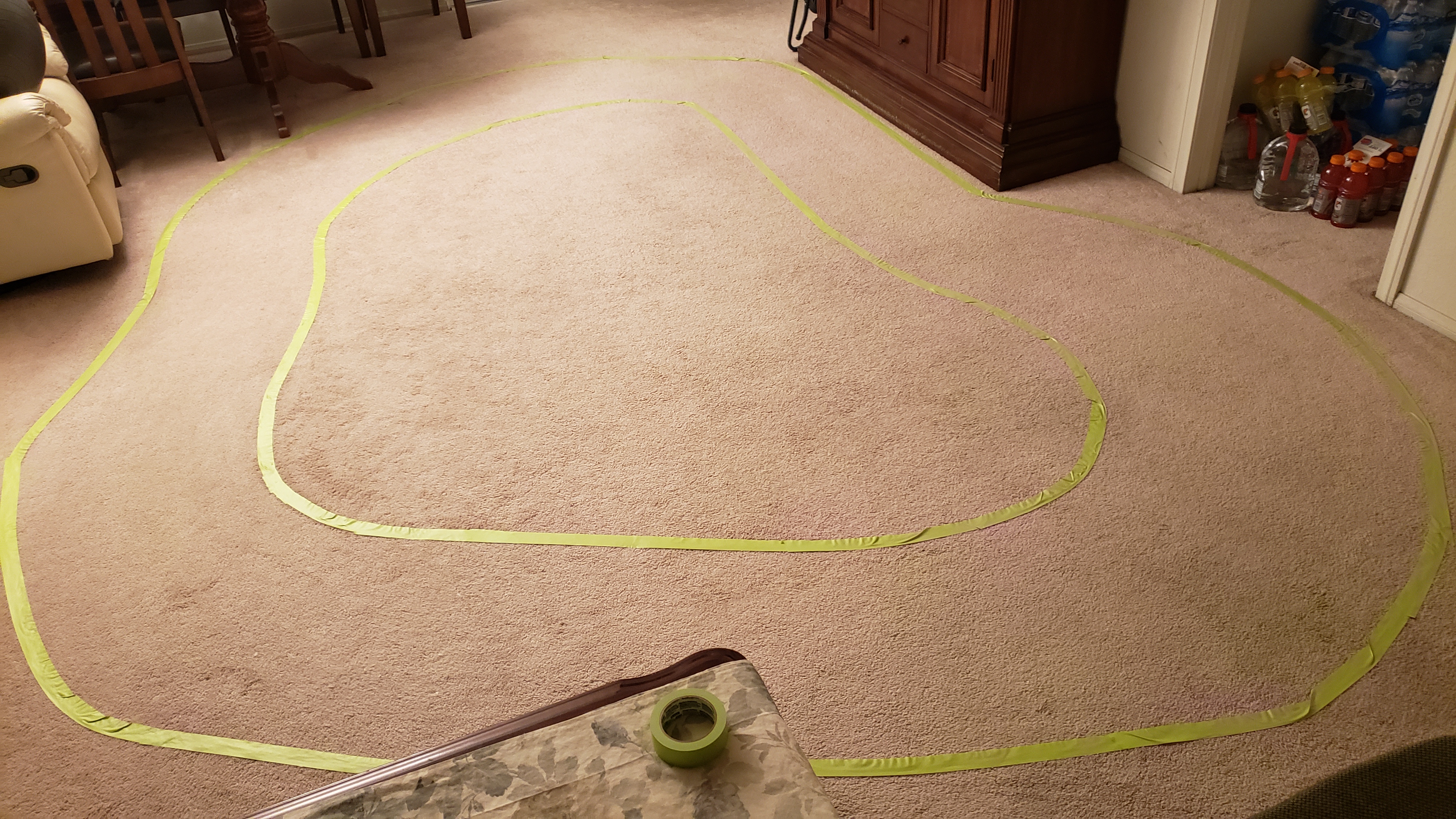
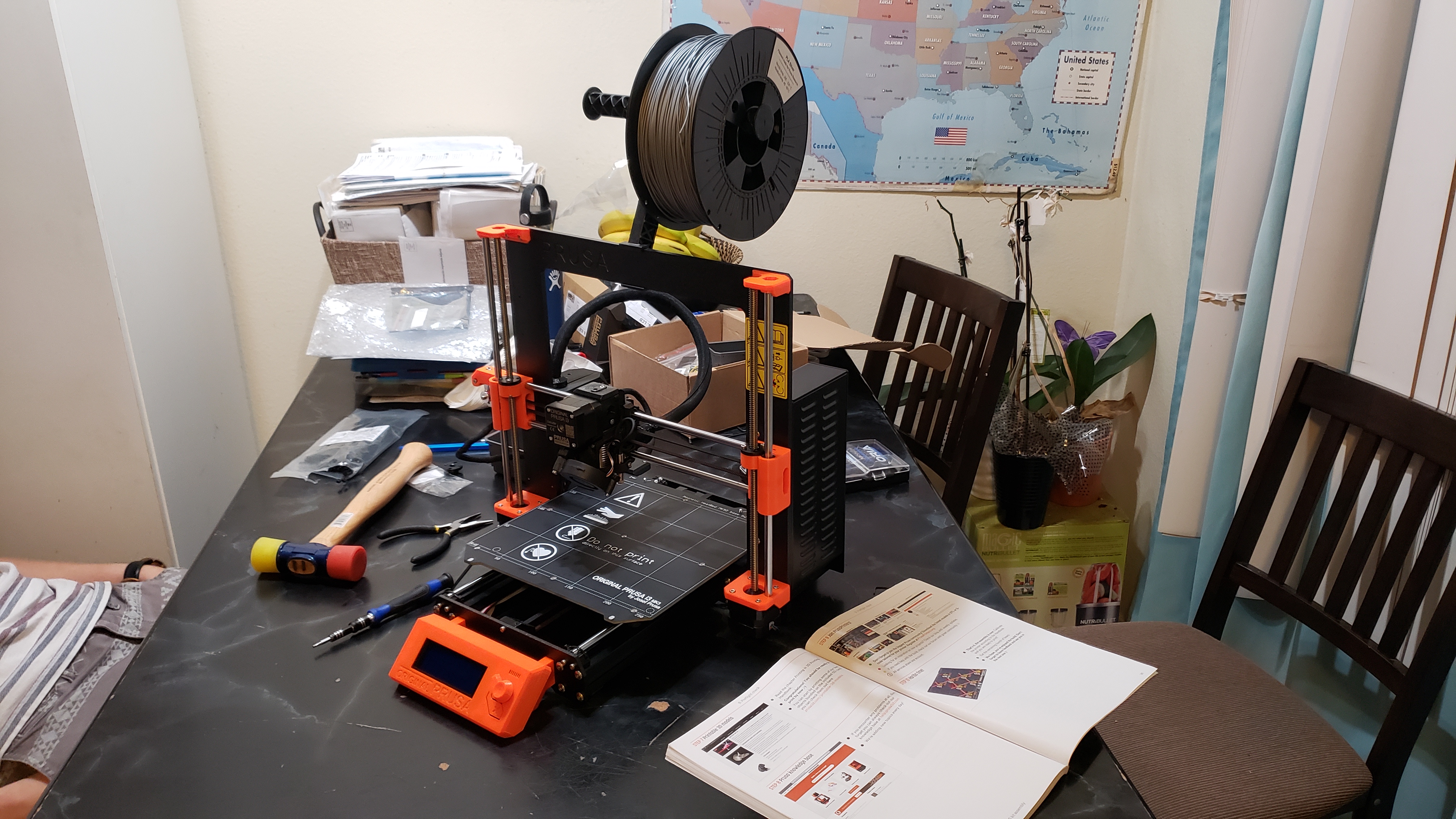
This is a small robot that can balance on two wheels using an arduino nano and an MPU6050 IMU. I built this robot by following a guide and
using spare parts I had from past projects which included everything except the chassis and the IMU. I designed the chassis in Solidworks
and then 3D printed it. After soldering all the necessary pieces and assembling the electronics onto the chassis, I calibrated the IMU and
uploaded the sketch given by the guide. From there, I manually tuned the PID values using a systematic and straightforward approach which involved:
setting all the gains to zero, increasing P until oscillations were occurring, increasing D to minimize those oscillations, and increasing
I to reduce the time to reach stabilization.
Overall, this was a fun and simple project that helped me to learn more about designing 3D printed parts and physically seeing the effects changing
PID values.
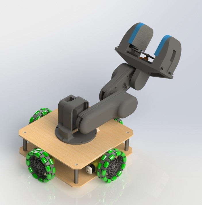
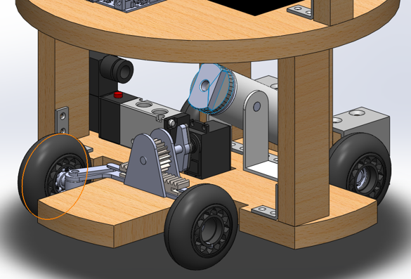
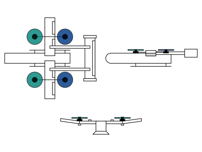
This is a 4 DOF arm with a gripper end effector designed to be placed on top of an RC car to pick up tennis balls. I was responsible for designing the arm structure including the base, the first linkage, and the second linkage. I designed this structure in SolidWorks with my main design considerations being safety, due to the future users being middle and high school students, and simplicity for the same reason.
The main challenge I faced with this project was maintaining the simplicity of the structure while being able to properly manage cables that came from the gripper, camera, and servos. These factors heavily shaped the design, and it taught me a lot about how certain requirements can control a large portion of the design work.
While in this project, I also played a part in developing a MATLAB simulation that would represent the team's control strategy for moving the end effector. This control strategy involved having a user input certain keys to move or rotate the end effector a set distance in a certain direction. Then using that desired end effector position, inverse kinematics would be used to relay information on how to rotate each of the linkage joints.
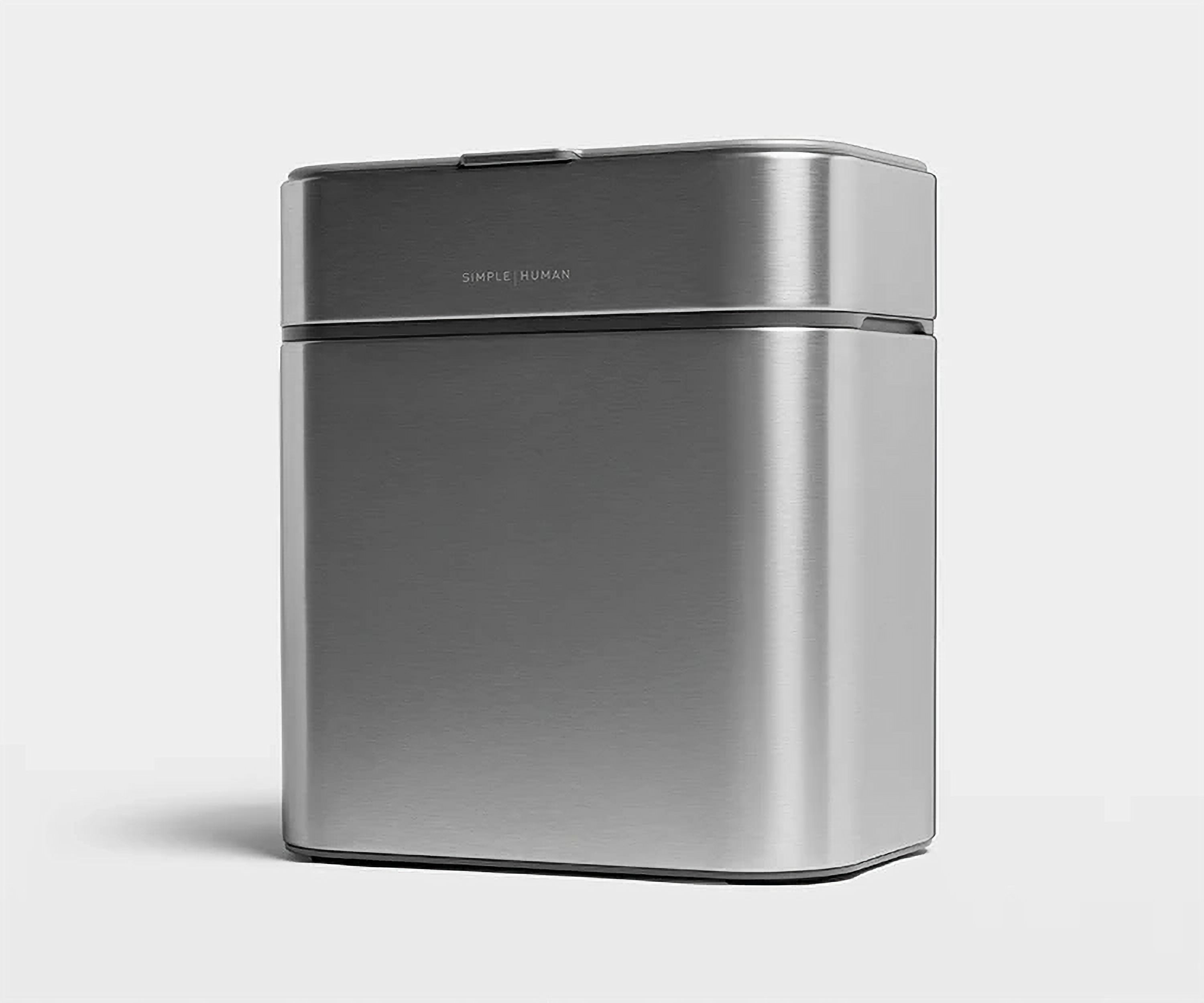
Shredder
During my role as lead mechanical engineer at simplehuman, I led the mechanical design of the simplehuman shredder, guiding the product from early concept through to full-scale production. Throughout development, I drove iterative design efforts, sourcing prototype components from local and overseas vendors, assembling and testing prototypes, and collaborating closely with hardware engineers, software engineers, quality engineers, industrial designers, and product leads to refine the design and user experience.
As the design neared finalization, I focused on Design for Manufacturing (DFM) and Design for Assembly (DFA), working directly with overseas manufacturers to ensure a seamless transition to production. I traveled internationally for pre-production and production trials to verify product functionality, optimize assembly efficiency, and resolve any last-minute manufacturing challenges.
This experience enhanced my capabilities as both a mechanical engineer and project leader, particularly in:
1. Hands-on prototyping 2. Mechanical design 3. Cross-functional team communication 4. DFM/DFA for plastic injection molding and sheet metal 5. UL regulation compliance
I took a hands-on approach to prototyping, utilizing in-house SLA/FDM 3D printers, laser cutters, and general shop tools for rapid iteration while sourcing CNC and sheet metal parts externally. By meticulously documenting and analyzing prototype issues, I distinguished between design-related and prototype-related flaws, allowing for targeted refinements. Through functional testing, I ensured the product met all performance requirements before advancing to the next stage.
By combining hands-on prototyping with iterative design improvements, I developed an intuitive understanding of how mechanical components interact in real-world conditions. This allowed me to identify potential design flaws before they became costly manufacturing issues. I also ensured that the final design was optimized for ease of assembly, reducing complexity while maintaining functionality and aesthetics.
Working closely with firmware, electrical, industrial design, and quality teams, I ensured that mechanical design decisions aligned with broader product requirements. Given the electromechanical nature of the product, I prioritized concise and proactive communication, keeping all stakeholders aligned before implementing design changes. Regular touchpoints and structured updates helped maintain momentum and prevent misalignment between teams.
As the product neared production, I collaborated with overseas manufacturers to refine plastic injection-molded and sheet metal components for scalable production. I worked closely with vendors to improve manufacturability while preserving product aesthetics and user experience. During pre-production trials, I verified part tolerances, assembly efficiency, and production consistency, addressing any issues that arose before full-scale manufacturing.
Finally, I learned how to navigate the UL certification process by collaborating with compliance consultants to review, test, and adjust the design to meet mechanical and electrical safety standards. I ensured all regulatory requirements were met for a seamless certification process.
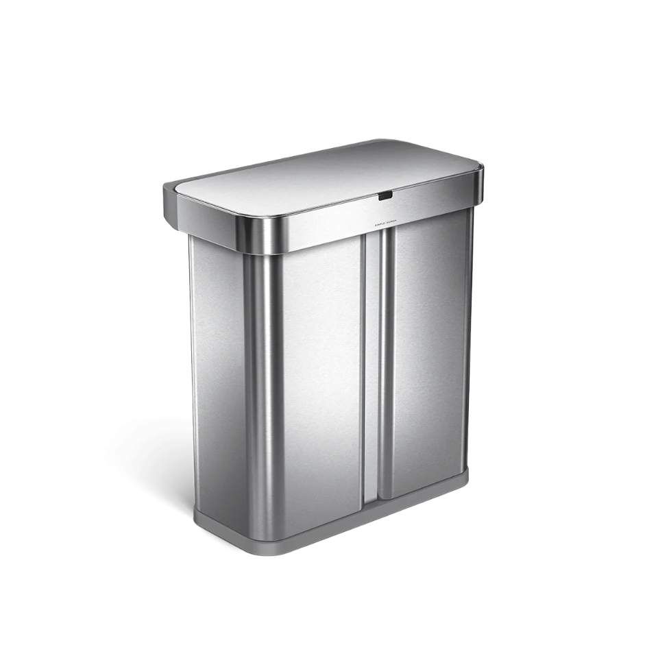
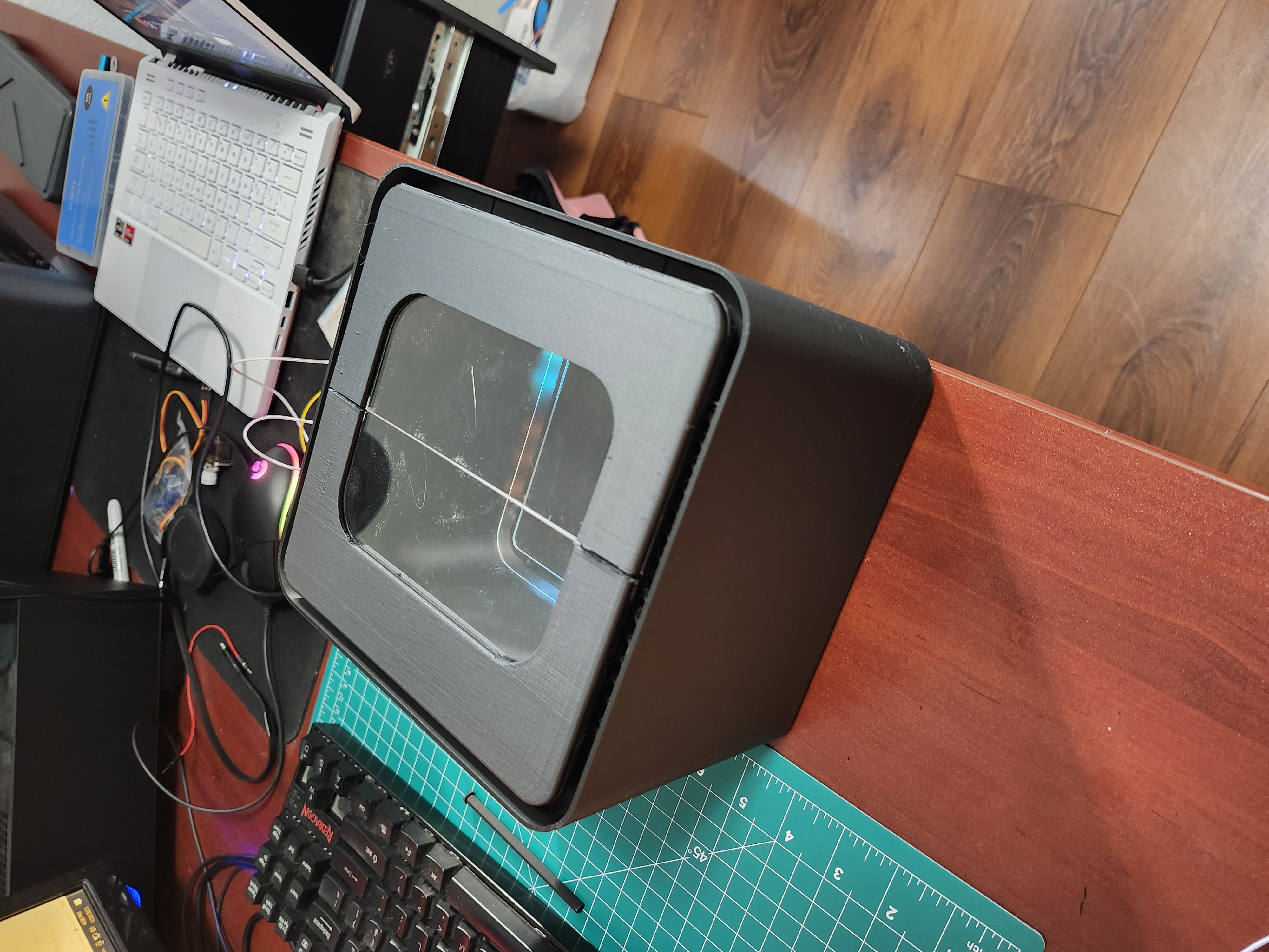
Sensor Can
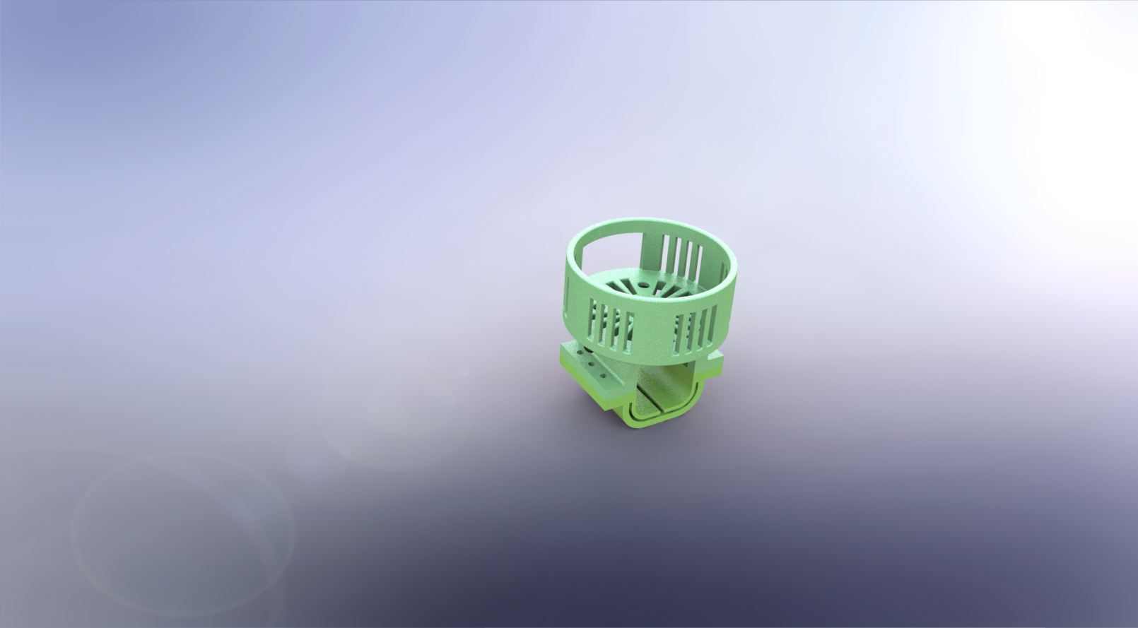
During my role as lead mechanical engineer at simplehuman, I led the mechanical design of the next-generation simplehuman sensor can, a complete revamp of the previous model aimed at enhancing product reliability and user experience. This redesign introduced new sensor technologies that had not yet been implemented in other simplehuman products, requiring extensive iterative testing and validation. I collaborated closely with software and hardware engineers to integrate these technologies while maintaining seamless functionality. Additionally, I worked with industrial designers, quality engineers, and external vendors to ensure mechanical improvements positively impacted both reliability and user interaction.
This project strengthened my expertise as both a mechanical engineer and project leader, particularly in:
1. Mechanical validation and testing
2. Mechanical design
3. Vendor communication
4. DFM/DFA for plastic injection molding and sheet metal
A key focus of the redesign was improving drive mechanism reliability while refining the lid's user interaction. In the previous model, if the lid opened under a desk, it would slam shut abruptly due to the lower strength of the internal mechanism. In contrast, the new design introduces a controlled soft-close in most standard user scenarios, only slamming if the user applies sufficient force. Though seemingly minor, this change required modifications to nearly every mechanical component within the drive mechanism.
1. For OTS components, I conducted technical discussions with suppliers to review our application, ensuring proposed modifications were both cost-effective and time-sensitive. Solutions often required coordinated design adjustments on both sides to meet reliability and performance targets.
2. For custom-designed parts, I collaborated with contract manufacturers to determine whether failures stemmed from design limitations or manufacturing inconsistencies. I then implemented targeted design updates or adjusted manufacturing parameters accordingly.
Throughout the refinement process, I worked alongside quality engineers, electrical engineers, and product leads to source, assemble, and test updated prototypes. Each iteration was subjected to rigorous lifecycle testing to ensure the changes met our high standards for durability and long-term reliability.
Misc.
(click back arrow to return)
Elements
Text
This is bold and this is strong. This is italic and this is emphasized.
This is superscript text and this is subscript text.
This is underlined and this is code: for (;;) { ... }. Finally, this is a link.
Heading Level 2
Heading Level 3
Heading Level 4
Heading Level 5
Heading Level 6
Blockquote
Fringilla nisl. Donec accumsan interdum nisi, quis tincidunt felis sagittis eget tempus euismod. Vestibulum ante ipsum primis in faucibus vestibulum. Blandit adipiscing eu felis iaculis volutpat ac adipiscing accumsan faucibus. Vestibulum ante ipsum primis in faucibus lorem ipsum dolor sit amet nullam adipiscing eu felis.
Preformatted
i = 0;

while (!deck.isInOrder()) {
    print 'Iteration ' + i;
    deck.shuffle();
    i++;
}

print 'It took ' + i + ' iterations to sort the deck.';